Why buy a UL Listed iDevices Switch when you can potentially electrocute yourself or start a fire with a self built alternative instead?
Here’s how!
First, you must install HomeBridge on a Raspberry Pi, and configure it as a HomeKit bridge device. Instructions below.
Once you have HomeKit / HomeBridge working on your Pi and your iPhone, we can build a wireless power switch that can be controlled by Siri and the HomeKit app.
We start with a PowerTail2, and use the ESP8266 to control the on/off line.
We power the ESP8266 with a AMS1117 3.3V Power Supply Module. This brings the 5v from the charger down to the proper 3.3v that the ESP8266 needs.
We provide the power with a used cell phone charger. 110v -> 5v. This is wired directly to the ‘Line’ side of the PowerTail2 circuit board. It is always ‘Live’ or ‘Hot’ and will shock you.
We Load the code into the ESP8266 via your favorite USB/Serial converter (FTDI).
We plug it in. Homekit sees the device via the HomeBridge configuration file addition (accessory) on the Raspberry Pi.
You control the device on your iPhone, and turn electricity on and off at will.
Step 3: ESP8266 Arduino Code
/* *  This sketch demonstrates how to set up a simple HTTP-like server.

 *  The server will set a GPIO pin depending on the request

 *    http://server_ip/gpio/0 will set the GPIO0 low,

 *    http://server_ip/gpio/1 will set the GPIO0 high

 *  server_ip is the IP address of the ESP8266 module, will be

 *  printed to Serial when the module is connected.

 */
// Start the server
server.begin();
//Serial.println("Server started");
// Print the IP address
//Serial.println(WiFi.localIP());
}
void loop() {
// Check if a client has connected
WiFiClient client = server.available();
if (!client) {
return;
}
// Wait until the client sends some data
//Serial.println("new client");
while(!client.available()){
delay(1);
}
// Read the first line of the request
String req = client.readStringUntil('\r');
//Serial.println(req);
client.flush();
// Match the request
int val;
if (req.indexOf("/gpio/0") != -1)
val = 0;
else if (req.indexOf("/gpio/1") != -1)
val = 1;
else {
//Serial.println("invalid request");
client.stop();
return;
}
// Set GPIO0 according to the request
digitalWrite(0, val);
digitalWrite(LED_BUILTIN, val); // Turn the LED on (Note that LOW is the voltage level
client.flush();
// Prepare the response
String s = "HTTP/1.1 200 OK\r\nContent-Type: text/html\r\n\r\n\r\n
\r\nGPIO is now ";
s += (val)?"high":"low";
s += "
\n";
// Send the response to the client
client.print(s);
delay(10);
//Serial.println("Client disonnected");
// The client will actually be disconnected
// when the function returns and 'client' object is detroyed
}
EvilRuxpin – The Chippy Ruxpin Alternative – Hacking a Teddy Ruxpin with Next Thing Co. C.H.I.P $9 Linux Computer to Play Heavy Metal
So, I modified a Chippy Ruxpin into a more ‘evil’ form as a gift for a coworker.
1. Build a Chippy Ruxpin out of a C.H.I.P. and an old Teddy Ruxpin
2. Make it evil. Make it say random evil scary things every few minutes, and make the eyes glow red with an LED
3. Make it wifi. It is now ad-hoc so no keyboard is needed. Smartphone controllable!
4. Add DHCP server, so your smartphone can connect and pull an IP, so you can load the web gui over wifi
5. Add an 3W stereo audio amplifier. Stock ruxpin speaker + CHIP audio is kinda wimpy. DC 5V PAM8403 Audio Stereo Amplifier Board Volume Control Class D Kit Module
6. Add a big battery, maybe a 5w solar panel to charge the battery.
7. put a heavy metal t shirt on Teddy.
8. option to play stored heavy metal .mp3’s using mplayer in linux, controllable on the webgui page from a smartphone.
I chose Blackened by Metallica as the first Heavy Metal song played thru a Teddy Ruxpin ever in the history of the Earth. Yes my Teddy Ruxpin plays Metallica in stereo on command via wifi from my smartphone.
Dont’ forget to put an .mp3 file in /home/chip/Desktop/m.mp3. Obviously we are going to change this to play many many metal .mp3’s. ‘Cause that’s rad. Teddy Ruxpin Metal Beats Pill. If only I could figure out how to make the mouth/eyes move while mplayer plays an .mp3…………hmmmmmmmmmmmmmm
9. do it all as a boot script so no user input is needed after power on.
I’ve done it! (except the LED/GPIO part)
More to come! to do:
to do: integrate amazon echo hack, so that replys move the mouth and eyes of Ruxpin.
So, here are the basic steps (updates to come):
–flash CHIP with 4.3 headless. 4.4 wifi? doesn’t seem to work even if you modify the GPIO variables in the .py script.
–enable a wifi connection, apt-get update and apt-get upgrade
–install all the chippy crap from the link below
-get chippy working
–apt-get install isc-dhcp-server, again see link below
–apt-get install bc , this lets ./battery.sh work, so you can monitory your LiPo 3.7v battery from linux
–apt install wireless-tools(this step may break your normal wifi managed mode connection setup. its ad-hoc w no internet from here out, so if you want to install more software from the internet, do it before this step)
edit /etc/NetworkManager/NetworkManager.conf: wired device not managed
Most probably your interface appears in /etc/network/interfaces. By default, NetworkManager does not manage interfaces that appear in /etc/network/interfaces. You can change this behaviour.
To do this – in a terminal:
sudo nano /etc/NetworkManager/NetworkManager.conf
change the line managed=false to managed=true
Save, stop and start network manager:
sudo service network-manager restart
-configure that bitch /etc/dhcp/dhcp.conf
-configure /etc/network something/ interfaces to use 192.168.1.66 ip and dns, see links below
-configure wlan0 to always use 192.168.1.66 because we are evil
-config wlan0 as ad-hoc wifi on channel 6 see just below this
-config /etc/rc.local to do all this crap at boot, no login needed to turn on wifi and dhcp, and python script
edit /etc/network/interfaces make the ip 192.168.1.66 cause we are evil:
source-directory /etc/network/interfaces.d
auto wlan0
iface wlan0 inet static
address 192.168.1.66
netmask 255.255.255.0
gateway 192.168.1.1
edit /etc/rc.local code:
iwconfig wlan0 mode ad-hoc channel 6 essid “EvilRuxpin”
ifconfig wlan0 up 192.168.1.66
sudo service isc-dhcp-server start
cd ChippyRuxpin cause i installed under root
python /root/ChippyRuxpin/chippyRuxpin.py
after a editing /etc/rc.local, /etc/network/interfaces and /etc/dhcp/dhcp.conf, reboot.
once booted up, you should be able to connect to ad-hoc wifi “EvilRuxpin”
it should serve up a DHCP address between 192.168.1.10-20.
goto http://192.168.1.66:8080 or 80
page should load
note: my stupid dell laptop would not connect to the ad-hoc wifi, but my iphone 5s would.
# IMPORTANT NOTE ABOUT TWITTER STUFF!
# In order to retrieve tweets, you need to authorize this code to use your twitter account.
# This involves obtaining some special tokens that are specific to you.
# Please visit Twitter’s website to obtain this information and put the values in the variables below.
# For more information, visit this URL:
# https://dev.twitter.com/oauth/overview/application-owner-access-tokens
consumerKey=’INSERT YOUR CONSUMER KEY HERE FROM TWITTER’
consumerSecret=’INSERT YOUR CONSUMER SECRET HERE FROM TWITTER’
accessTokenKey=’INSERT YOUR ACCESS TOKEN KEY HERE FROM TWITTER’
accessTokenSecret=’INSERT YOUR ACCESS TOKEN SECRET HERE FROM TWITTER’
import sys
import time
import subprocess
import os
from random import randint
from threading import Thread
from chippyRuxpin_audioPlayer import AudioPlayer
from chippyRuxpin_gpio import GPIO
from chippyRuxpin_twitter import ChippyTwitter
from chippyRuxpin_webFramework import WebFramework
fullMsg = “”
MOUTH_OPEN = 408 # GPIO pin assigned to open the mouth. XIO-P0
MOUTH_CLOSE = 412 # GPIO pin assigned to close the mouth. XIO-P2
EYES_OPEN = 410 # GPIO pin assigned to open the eyes. XIO-P4
EYES_CLOSE = 414 # GPIO pin assigned to close the eyes. XIO-P6
while isRunning:
#cmd = “sudo sh -c ‘echo 1 > /sys/class/gpio/gpio412/value'”
#subprocess.Popen(cmd,shell=True, stdout=subprocess.PIPE)
time.sleep(1)
global rcount
myTextIndex = 1
rcount = rcount + 1
myTextIndex = ( randint( 0,2) )
print(myTextIndex)
print(rcount)
if rcount >= 60:
#myTextIndex == 0
if myTextIndex == 0:
myText = “hello fucker!”
elif myTextIndex == 1:
myText = “I can hear you Adam. I know you are talking about me. You don’t want to make me angry ”
elif myTextIndex == 2:
myText = “Hey! give me the pipe back”
else:
myText = ‘single quotes this is option 4’
#return MyText
rcount = 0
talk(myText)
chippyRuxpin-webFramework.py:
#!/usr/bin/env python

#

# Chippy Ruxpin by Next Thing Co 2015

# Powered by C.H.I.P., the world's first $9 computer!
from bottle import run, get, post, request, route, redirect
import socket
preset1=”Hello Adam, would you like to hear some Heavy Metal?”
preset2=”Hello Adam, would you like to hear some Heavy Metal?”
print(“web start”)
class WebFramework:
def __init__(self,func):
self.ip = [(s.connect((‘192.168.1.66’, 80)), s.getsockname()[0], s.close()) for s in [socket.socket(socket.AF_INET, socket.SOCK_DGRAM)]][0][1]
print( “———“)
print( “CHIPPY RUXPIN IS ONLINE!”)
print( “In your browser, go to ” + str(self.ip) + “:8080”)
print( “———“)
self.talkFunc = func
this part of the code does not format well in wordpress . it is: LESS THAN SYMBOL form action=”/” method=”post” GREATER THAN SYMBOL
preset11: LESS THAN SYMBOL input name=”speech” type=”text” size=”96″ value=”one of these days, _ _ _ _ I am going to kill that fucking cat'” / GREATER THAN SYMBOL
LESS THAN SYMBOL input value=”Go!” type=”submit” / GREATER THAN SYMBOL
chippyRuxpin_audioPlayer.py:
#!/usr/bin/env python

#

# Chippy Ruxpin by Next Thing Co 2015

# Powered by C.H.I.P., the world's first $9 computer!
#!/usr/bin/env python
#
import alsaaudio as aa
import audioop
from time import sleep
import struct
import math
import array
import numpy as np
import wave
import os
import subprocess
class AudioPlayer:
def __init__(self):
subprocess.Popen(‘amixer cset numid=1 100%’ ,shell=True, stdout=subprocess.PIPE ) # Set PA mixer volume to 100%
subprocess.Popen(‘amixer cset numid=2 2’ ,shell=True, stdout=subprocess.PIPE ) # Set right mixer to be “right” (2)
subprocess.Popen(‘amixer cset numid=3 1’ ,shell=True, stdout=subprocess.PIPE ) # Set left mixer to be “left” (1)
subprocess.Popen(‘amixer cset numid=4 1′ ,shell=True, stdout=subprocess.PIPE ) # Set DAC self.output to be “Direct” (2… or 1 for “Mixed” if you prefer)
self.prevAudiovalue = 0
self.mouthValue = 0
The original code is for an Arduino YUN. The YUNs have built in ethernet and some code had to be changed to get it to work with my standard Uno with an ethernet shield.
Basically i had to strip out the Console.print and the Bridge.h commands, changing them to Serial.print . Also ,I had to shift the response string lookup digits a few places, because it was offset with the original YUN code. I just copied the RESPONSE from the serial monitor into Notepad, and counted the digits by using the right arrow key, taking note to count the spaces as well.
Here is the modified code that works on an Arduino Uno with an Ethernet shield. Dont forget to get your TembooAccount.h file from the temboo site.
Also, I had issues with the header code box not populating correctly while following the instructions. Try hitting refresh, switch between Arduino YUN and Arduino code using the box at the top of the temboo website.
You will need to edit the code below to include YOUR twilio auth code and ID. This code will turn a LED on digital pin7 if you send a text as “lights on” and turn the led off if you send “lights off”
/* Setup shield-specific #include statements */

/*Use the pic above, for the header setup, my WordPress software hides the code from this part in this post */

#include

#include

#include

#include

#include

#include

#include "TembooAccount.h" // Contains Temboo account information

#include
/*REPLACE THE FIRST 10 Lines with those shown in the pic above ^ */
int numRuns = 1; // Execution count, so this doesn't run forever
int maxRuns = 5; // Maximum number of times the Choreo should be executed
int ledPin = 13; // Led for debug
int buzzerPin = 2; // buzzer's connected to pin 2
int lightsPin = 7; // The pin where your Xmas lights are connected to.
int timeToWait = 600000; //Delay between calls
String bodyMsgLast = "none"; // This variable holds the last text message read.
void setup() {
Serial.begin(9600);
// For debugging, wait until the serial console is connected.
delay(4000);
while(!Serial);
//Turn lights off on boot up
digitalWrite(lightsPin, HIGH);
delay(5000); //simulates a button press for 5 seconds
digitalWrite(lightsPin, LOW);
delay(1000);
//Bridge.begin();
//Console.begin();
}
void loop() {
if (numRuns <= maxRuns) {
Serial.println("Running GetLastMessageThatContains - Run #" + String(numRuns++));
TembooChoreo GetLastMessageThatContainsChoreo(client);
// Invoke the Temboo client
GetLastMessageThatContainsChoreo.begin();
// Set Temboo account credentials
GetLastMessageThatContainsChoreo.setAccountName(TEMBOO_ACCOUNT);
GetLastMessageThatContainsChoreo.setAppKeyName(TEMBOO_APP_KEY_NAME);
GetLastMessageThatContainsChoreo.setAppKey(TEMBOO_APP_KEY);
// Set Choreo inputs
String AuthTokenValue = "6e0aecedb5461c4ccbc7f72535c7c569";
GetLastMessageThatContainsChoreo.addInput("AuthToken", AuthTokenValue);
String FilterValue = "lights";
GetLastMessageThatContainsChoreo.addInput("Filter", FilterValue);
String AccountSIDValue = "AC25eb0f996fbe268825f00405885f6fba";
GetLastMessageThatContainsChoreo.addInput("AccountSID", AccountSIDValue);
// Set Choreo inputs
GetLastMessageThatContainsChoreo.addInput("AuthToken", " PUT YOUR TWILIO AUTH TOKEN HERE "); //Twilio Authentication Token
GetLastMessageThatContainsChoreo.addInput("Filter", "ights"); // Filter for incoming messages holding this word
GetLastMessageThatContainsChoreo.addInput("AccountSID", " PUT YOUR TWILIO ACCOUNT ID HERE "); //Twilio account ID
GetLastMessageThatContainsChoreo.addInput("ResponseMode", "simple"); //Response Mode
// Identify the Choreo to run
GetLastMessageThatContainsChoreo.setChoreo("/Library/Twilio/SMSMessages/GetLastMessageThatContains");
// Run the Choreo; when results are available, print them to serial
GetLastMessageThatContainsChoreo.run();
String bodyMsg; // This contains the whole Message
while(GetLastMessageThatContainsChoreo.available()) {
char c = GetLastMessageThatContainsChoreo.read();
Serial.print(c);
bodyMsg += c; //The characters are being fed to the bodyMsg string
}
//Serial.println(bodyMsg+ "<-- is bodyMsg" );
if (bodyMsg != bodyMsgLast) { //Only runs if this message is different than the one stored.
if (bodyMsg.substring(33, 35) == "on") { //This only works if the 17th to 19 letters are "on"".
// This works if you're seinding the message "Lights on"
// Characters before Lights on are other info from Twilio
// Turn lights on
//digitalWrite(ledPin, HIGH); //turns on debug LED
digitalWrite(lightsPin, HIGH);
//delay(800);
//digitalWrite(lightsPin, LOW); //Simulated button press for less than a second
Serial.println("Lights are on");
//tone(buzzerPin, 2000, 3000); //beeps for 3 seconds
} else if (bodyMsg.substring (33, 36) == "off") { //17 20reads "off" from a message saying "Lights off"
//digitalWrite(ledPin, LOW); //turns off debug LED
//tone(buzzerPin, 4200, 1000); //beeps
digitalWrite(lightsPin, LOW);
//delay(5000); //simulates a 5 second button press to turn the lights off
//digitalWrite(lightsPin, LOW);
//delay(1000);
Serial.println("Lights are off");
}
bodyMsgLast = bodyMsg; //Copies this message to the Last message variable
} else {
Serial.println("Identical to Last"); //if identical, do nothing.
}
Serial.println();
Serial.println("Waiting...");
delay(timeToWait); // wait a period between GetLastMessageThatContains calls
GetLastMessageThatContainsChoreo.close();
}
Serial.println("\nWaiting...\n");
delay(30000); // wait 30 seconds between GetLastMessageThatContains calls
}
TembooAccount.h
you must edit your tembooaccount.h file as well. make sure you get an up to date app key FOR YOUR APP from the temboo website.
/*

IMPORTANT NOTE about TembooAccount.h
TembooAccount.h contains your Temboo account information and must be included
alongside your sketch. To do so, make a new tab in Arduino, call it TembooAccount.h,
and copy this content into it.
*/
#define TEMBOO_ACCOUNT "lagunabeachcomputer" // Your Temboo account name
#define TEMBOO_APP_KEY_NAME "myFirstApp" // Your Temboo app key name
#define TEMBOO_APP_KEY "2761f18fae384543af4f... xxxx " // Your Temboo app key
/*
The same TembooAccount.h file settings can be used for all Temboo SDK sketches.
Keeping your account information in a separate file means you can share the
main .ino file without worrying that you forgot to delete your credentials.
*/
I decided to keep the J1 resistor and C114 capacitor as they orignally were after reading some comments suggesting the signal strength would be better leaving them alone.
Step 3. Solder on Antenna Pigtail Cable. My cable was scavenged from a broken cheapie $5 USB Wifi adapter. The soldering was hard. It is just really small down there. Here is a trick: put a blob of solder on the tip of your hot iron. Now smear that melted blob OFF onto a dry sponge. Now you should be able to PICK UP a SMALLER BLOB of solder and place it where you want.
I used tape to hold down the wire. As you bend the cable, it puts a lot of tension on the two little solder points. If you do not hold down the wire somehow, your precious little solders will eventually break off. Since the tape will eventually fail, it would be far better to hold the wire down with a blob of hot glue gun stuff.
Step 4. Insulate, Assemble and Test.Make sure you insulate the two little R82 resistors under the antenna fitting metal. You do not want to short out the circuit board with the metal from the antenna screw fitting inside the case. A small piece of sturdy electrical tape under the brass nut should cover and protect R82.
This updated code removes the switch seen in the video and makes the motor spin automatically about .5 degrees every second. Here is the beta Arduino code sketch:
#include <SoftwareSerial.h>
/*
* Switch and LED test program
*/
int ledPin = 5; // LED is connected to pin 12
int switchPin = 0; // switch is connected to pin 2
int val; // variable for reading the pin status
int ledPin6 = 6; // LED is connected to pin 12
int switchPin1 = 1; // switch is connected to pin 2
int val1; // variable for reading the pin status
void setup() {
pinMode(ledPin, OUTPUT); // Set the LED pin as output
pinMode(switchPin, INPUT); // Set the switch pin as input
pinMode(ledPin6, OUTPUT); // Set the LED pin as output
pinMode(switchPin1, INPUT); // Set the switch pin as input
//Setup Channel A
pinMode(12, OUTPUT); //Initiates Motor Channel A pin
pinMode(9, OUTPUT); //Initiates Brake Channel A pin
}
void loop(){
//delay(10);
//val = digitalRead(switchPin); // read input value and store it in val
//if (val == LOW) { // check if the button is pressed
//digitalWrite(ledPin, HIGH); // turn LED on
//Serial.begin(9600); // set up Serial library at 9600 bps
//Serial.print(“sw0 on: “);Serial.println(digitalRead(switchPin));
//forward @ full speed
digitalWrite(12, HIGH); //Establishes forward direction of Channel A
digitalWrite(9, LOW); //Disengage the Brake for Channel A
analogWrite(3, 200); //Spins the motor on Channel A at full speed
delay(.1); //// ***** THIS SETS THE ROTATION SPEED .1 is good for slow spin, 10 or 100+ will rotate further
//delay(10);
// }
if (val == HIGH) { // check if the button is not pressed
digitalWrite(ledPin, LOW); // turn LED off
delay(10);
digitalWrite(9, HIGH); //Eengage the Brake for Channel A
//delay(1000);
}
// delay(10);
val = digitalRead(switchPin1); // read input value and store it in val
if (val == LOW) { // check if the button is pressed
digitalWrite(ledPin6, HIGH); // turn LED on
//Serial.print(“on: “);Serial.println(digitalRead(switchPin1));
//backward @ half speed
digitalWrite(12, LOW); //Establishes backward direction of Channel A
digitalWrite(9, LOW); //Disengage the Brake for Channel A
analogWrite(3, 255); //Spins the motor on Channel A at half speed
delay(3000);
delay(10);
}
if (val == HIGH) { // check if the button is not pressed
digitalWrite(ledPin6, LOW); // turn LED off
//Serial.print(“1=off: “);Serial.println(digitalRead(switchPin1));
digitalWrite(9, HIGH); //Eengage the Brake for Channel A
delay(1000);
delay(10);
}
}
I plan on adding a potentiometer to control the rotation speed.
Here is the Arduino Sketch code I wrote for the tracker:
int lightPin = A0; //define a pin for Photo resistor
int ledPin=6; //define a pin for LED
int val= 1;
int lightPin1 = A1; //define a pin for Photo resistor
int ledPin5=5; //define a pin for LED
int val1= 1;
int setPoint19 = 20; // Trigger value
int setPoint25 = 25; // Trigger value
int setPoint29 = 29; // Trigger value
int setPoint35 = 35; // Trigger value
if (val < setPoint35)
{
analogWrite(ledPin, LOW); // It has got dark, turn the LED on.
}
else
{
analogWrite(ledPin, 255); // It is light again, turn the LED off.
}
Serial.print("val = ");
Serial.print(val ) ; //Write the value of the photoresistor to the serial monitor.
Serial.print(" lightPin = ");
Serial.print(analogRead(lightPin));
Serial.print(" lightPin /4-1= ");
Serial.println(analogRead(lightPin)/4-1); //Write the value of the photoresistor to the serial monitor.
//analogWrite(ledPin, val); //send the value to the ledPin. Depending on value of resistor
//you have to divide the value. for example,
//with a 10k resistor divide the value by 2, for 100k resistor divide by 4.
//Serial.println(analogRead(lightPin)/3); //Write the value of the photoresistor to the serial monitor.
delay(10); //short delay for faster response to light.
val1 = (analogRead(lightPin1)*1);
if (val1 < setPoint35)
{
analogWrite(ledPin5, LOW); // It has got dark, turn the LED on.
}
else
{
analogWrite(ledPin5, 255); // It is light again, turn the LED off.
}
Serial.print("val1= ");
Serial.print(val1 ) ; //Write the value of the photoresistor to the serial monitor.
Serial.print(" lightPin1= ");
Serial.print(analogRead(lightPin1));
Serial.print(" lightPin1/4-1= ");
Serial.println(analogRead(lightPin1)/4-1); //Write the value of the photoresistor to the serial monitor.
//analogWrite(ledPin, val); //send the value to the ledPin. Depending on value of resistor
//you have to divide the value. for example,
//with a 10k resistor divide the value by 2, for 100k resistor divide by 4.
//Serial.println(analogRead(lightPin)/3); //Write the value of the photoresistor to the serial monitor.
delay(10); //short delay for faster response to light.
}
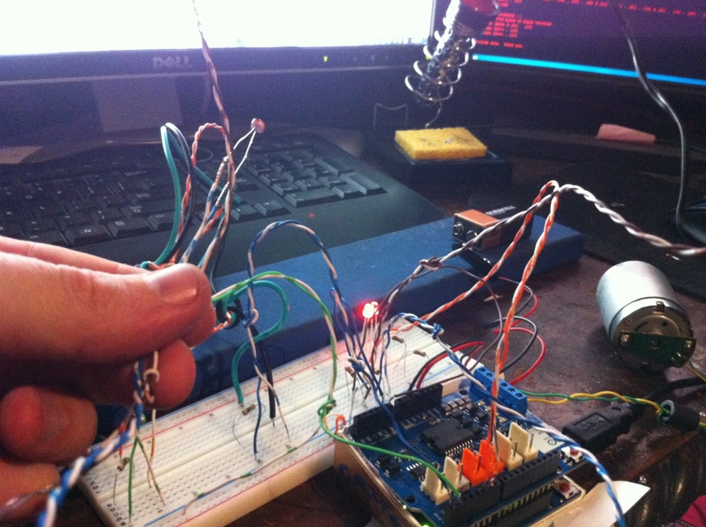
Arduino Solar Tracker
Here is the Arduino sketch code I wrote that will move a 2-wire DC motor forward and reverse depending on which of 2 buttons is pressed:
#include
/*
* Switch and LED test program
*/
int ledPin = 5; // LED is connected to pin 12
int switchPin = 0; // switch is connected to pin 2
int val; // variable for reading the pin status
int ledPin6 = 6; // LED is connected to pin 12
int switchPin1 = 1; // switch is connected to pin 2
int val1; // variable for reading the pin status
void setup() {
pinMode(ledPin, OUTPUT); // Set the LED pin as output
pinMode(switchPin, INPUT); // Set the switch pin as input
pinMode(ledPin6, OUTPUT); // Set the LED pin as output
pinMode(switchPin1, INPUT); // Set the switch pin as input
//Setup Channel A
pinMode(12, OUTPUT); //Initiates Motor Channel A pin
pinMode(9, OUTPUT); //Initiates Brake Channel A pin
}
void loop(){
delay(10);
val = digitalRead(switchPin); // read input value and store it in val
if (val == LOW) { // check if the button is pressed
digitalWrite(ledPin, HIGH); // turn LED on
//Serial.begin(9600); // set up Serial library at 9600 bps
//Serial.print("sw0 on: ");Serial.println(digitalRead(switchPin));
//forward @ full speed
digitalWrite(12, HIGH); //Establishes forward direction of Channel A
digitalWrite(9, LOW); //Disengage the Brake for Channel A
analogWrite(3, 255); //Spins the motor on Channel A at full speed
delay(3000);
//delay(10);
}
if (val == HIGH) { // check if the button is not pressed
digitalWrite(ledPin, LOW); // turn LED off
delay(10);
digitalWrite(9, HIGH); //Eengage the Brake for Channel A
//delay(1000);
}
delay(10);
val = digitalRead(switchPin1); // read input value and store it in val
if (val == LOW) { // check if the button is pressed
digitalWrite(ledPin6, HIGH); // turn LED on
//Serial.print("on: ");Serial.println(digitalRead(switchPin1));
//backward @ half speed
digitalWrite(12, LOW); //Establishes backward direction of Channel A
digitalWrite(9, LOW); //Disengage the Brake for Channel A
analogWrite(3, 255); //Spins the motor on Channel A at half speed
delay(3000);
delay(10);
}
if (val == HIGH) { // check if the button is not pressed
digitalWrite(ledPin6, LOW); // turn LED off
//Serial.print("1=off: ");Serial.println(digitalRead(switchPin1));
digitalWrite(9, HIGH); //Eengage the Brake for Channel A
I’m building the circuit now. Got the Teensy micro controller for the prjc store. The capacitors and resistors I got off eBay for less than $5 delivered. I will note that I should have bought a half sized breadboard, this one won’t fit in the USB hub case I’m going to use to encase the 3dpVert circuit.